about Audio, High Fidelity
& Home Entertainment technologies
pid: 623-2026/01/21 (v1.2)
Privacy Policy

Laboratory evaluation of 121 has been primarily done through the S/PDIF using 24bit/96kHz signals (except otherwise stated).
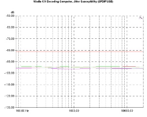
The converter proved to be jitter tolerant for signals through both S/PDIF input and the USB port, the second one being marginally better for signals in the low and middle frequencies. The relevant distortion curves lie around -95dB (for 500Hz/997Hz) and slightly higher, near -80dB for 24kHz.
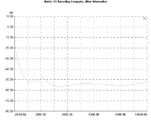
Wadia jitter attenuation method seems to have good results, as the relevant graph appears to be between -50 and -60dB for the largest part of the jitter spectrum, its efficiency reduced gradually below 1000Hz.
Jitter susceptibility. Signal level:-3dBFS, sample rate 96kHz, S/PDIF input, sinusoidal jitter 40nS, Fs/192 (green curve), 997Hz (red), Fs/4 (orange). USB input, sinusoidal jitter 40nS, Fs/192 (magenta curve), 997Hz (purple), Fs/4 (pink).
Jitter attenuation. Signal jitter 80nS pp, S/PDIF input.
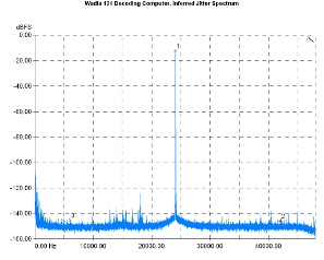
Jitter introduced by the device itself seems to be quite low. Calculation based on spectrum sidebands lead to a value of about 8.7pS/6kHz.
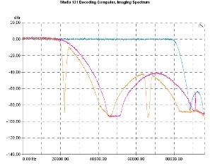
Frequency response (using wideband noise) near and above the cut off points shows that Wadia has chosen a typical behavior for the 44.1kHz sample rate and, rather curiously, a low slope response (at the expense of bandwidth) for the 96kHz sample rate. This approach denies the 121 a higher bandwidth for the 96kHz sample rate. When 176.4kHz sample rate is used, on the other hand, things are return to normality, with an almost up to the theoretically permissible limit bandwidth. The logic behind these choices is not clear (and the company does not make any reference) but somewhat highlights the lack of user selectable filters.
Intrinsic jitter spectrum. Input Signal : 24kHz/-5dBFS.
Low pass filter response. 44.1kHz (orange curve), 96kHz (violet), 176.4kHz (blue).
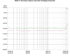
In any case, the filters chosen by the Wadia seems to operate effectively as expected. At 96kHz, the suppression of aliasing products appears to be around -100dBFS.
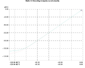
Level linearity was satisfactory, with the relevant curves maintain the ideal form down to around -90dBFS, a point from which a gradual deviation could be observed.
Suppression of imaging components. Sample rate 96kHz.
Output level linearity. Signal frequency 1kHz.
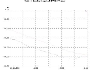
The distortion vs level diagram shows a device with good behavior, with the THD+N curve just below the -40dB at a -60dBFS signal level and the THD curve distortion around -60dB at the same signal level.
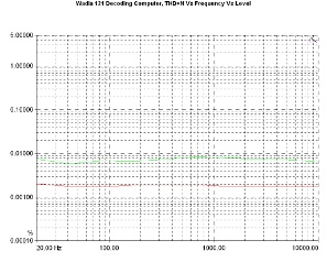
Similarly good behavior is noted in the THD+N Vs Frequency diagram. With the output level near its maximum (-1dBFS) the relevant curve lies just below 0.002% while in lower output levels this figure rises near 0.007%. This is evidence towards an analogue stage without overload problems.
THD and THD+N Vs level. Sample rate 96kHz, THD+N (pink), THD (purple).
THD+N Vs Frequency. Sample rate 96kHz. Signal Level: -1dBFS (red curve), -20dBFS (green).
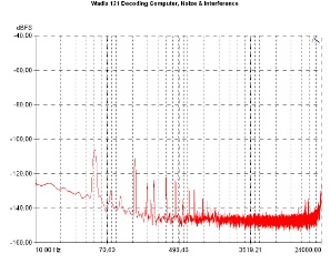
In-band noise appears to be low in general, with the idling channel noise below -120dBFS both in the mid and high frequencies and a peak at the 50Hz hum region. Near the 20kHz limit the noise rises just above -120dBFS.
The wideband noise spectrum shows a device with low noise in the high frequency region. Basic source of noise appears to be the power supply.
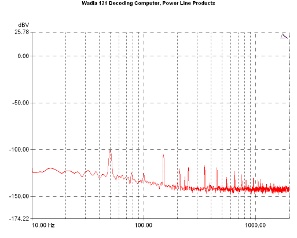
Static measurements of the power line related noise was about -110dBFS and -104.5dBFS for the right and the left channel respectively, these figures being equivalent to 6uVrms and to 11uVrms. Power line noise spectrum analysis points to the power grid frequency and some intermodulation products as the basic noise sources, all of them with amplitude below -100dBFS.
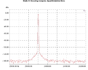
Signal modulation noise appears to be quite low, with the relevant graph showing no intermodulation lobes at the 50/100Hz points. There are some very low frequency modulation traces though, in the vicinity of the test signal.
Power line related noise components.
Signal modulation noise. Reference signal : 23.950,20 Hz, 24bit/96kHz.
Channel crosstalk was good, with both the relevant curves bellow -100dΒ and towards -110dB, except in the very low frequency region (below 100Ηz). A difference between the two channels in the mid region (about 10dB) could be the result of the different noise signatures showed.

