about Audio, High Fidelity
& Home Entertainment technologies
pid: 607-2025/10/01 (v1.2)
Privacy Policy
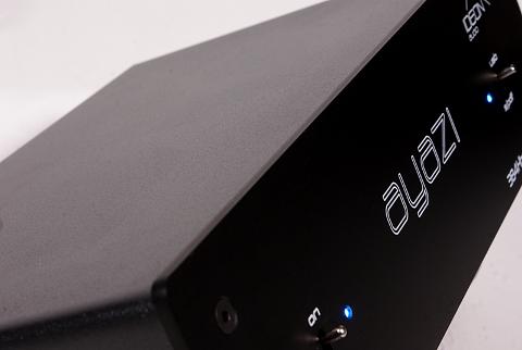
Lab evaluation of the Ayazi was performed through its coaxial input with both 24/96 and 24/192 signals unless stated otherwise.
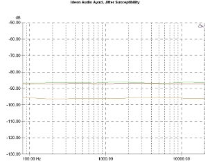
The behavior of the digital interface justified Ideon's choice as the device appears to be quite resilient to incoming signals with jitter. The relevant graphs were in the -90/-100dB range, a behavior which certainly can be considered as very good.
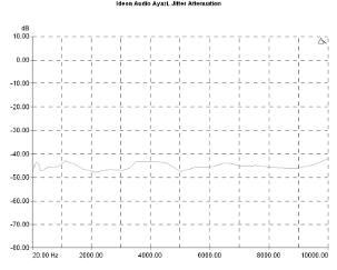
Similarly, good behavior was noted in the incoming jitter attenuation capacity for signals through the coaxial input. The relevant graph is located in the -45dB range, a clue that the overall design offers some significant jitter rejection (and, therefore, one could use a jittery digital source with some confidence).
Jitter susceptibility. 96kHz sample rate, -3dBFS signal with 40nS sinusoidal jitter injected, FS/192 (green curve), 997Hz (red), FS/4 (Orange).
Jitter attenuation vs jitter frequency. Signal 10kHz, injected jitter 80nS p-p.
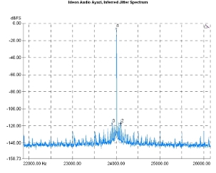
Overall, the device seems to introduce only low levels of jitter, the estimation varying between 56 and 160pS in the low-frequency range and declining at higher frequency values.
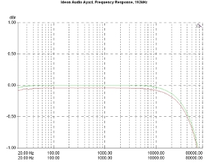
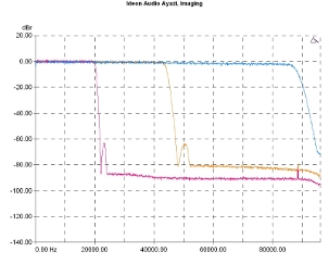
The frequency response was, as expected, without any problems. The converter is practically flat up to 40kHz (-0.5dBr), with a very smooth roll-off up to 60kHz (-1dB). Channel balance should be considered as excellent, being less than 0.1dB across the entire range of the measurement.
The behavior of the converter around and above the cutoff frequency of the low-pass filter is typically good. Stop-band ripple was small (with a visible peak below -60dBr) and the total cut-off area seems very quiet.
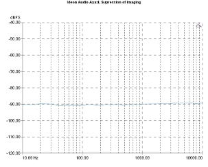
This good behavior has positive in-band consequences since the suppression of sampling by-products is very good with the graph lying at -90dBFS without any increasing trend towards the upper limit of the measurement (at 10kHz).
Low pass filter response. 44.1kHz (orange curve), 96kHz (violet curve), 192kHz (blue).
Suppression of imaging components (96kHz sample rate).
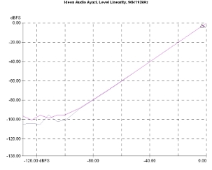
Level linearity remained at levels typically good for the price range. The relevant graphs (for 96kHz and 192kHz sample rates) retain their ideal form until down to -90dBFS approximately, while the graph flattens out near the -100dBFS.
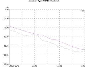
Distortion Vs Level measurements were, also, typically good. Both the harmonic distortion and total harmonic distortion and noise increase as the signal level decreases and at -60dBFS lie around -40dB, a performance which should be regarded as good. Close to the maximum output level, the output stage (the one that the ES9023 chip includes) seems to have no problems. The distortion shows an upward trend but it remains at very low levels (close to -90dB at the maximum output level of the device).
Output level linearity. Signal frequency 1kHz, sample rate 96kHz., S/PDIF input, 96kHz (pink curve), 192kHz (purple).
THD/THD+N Vs Output level. Sample rate 96kHz, input S/PDIF, THD+N (pink curve), THD (purple).
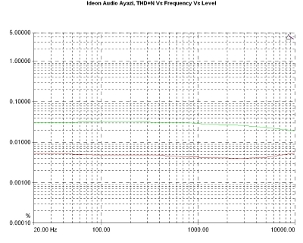
The THD+N Vs Frequency graph reveals a circuit with good behavior. For low-level signals (where noise plays a role), the distortion and noise were around 0.03%, while for high-level output signals close to the device maximum output level, THD+N was about 0.005%, for the whole measurement bandwidth with a slight upward trend near 10kHz.
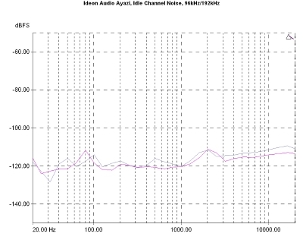
Ayazi noise measurements reveal a very quiet design. Idling channel noise is under -110dBFS slightly increasing at high frequencies (near the 20kHz limit). There is, also, a difference in behavior between sample rates above about 3kHz, with the converter being slightly better at 192kHz.
THD+N Vs frequency. Sample rate 96kHz, input S/PDIF. Level: -1dBFS, (red curve) and -20dBFS (green).
Idle channel noise spectrum. S/PDIF input, 96kHz (purple curve), 192kHz (pink).
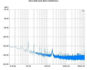
The noise spectrum contains some visible components from the mains (but at very low levels overall, the noise from the power supply not exceeding 10uVrms) and minimal presence of high-frequency components.
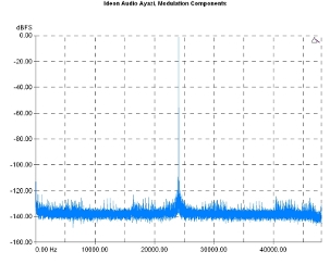
Signal modulation noise was also quite low. The broadband measurement graph contains some traces of intermodulation, mainly from low-frequency noise signals but these are at very low levels.
Noise and interference spectrum (broadband).
Signal modulation noise (broadband). Reference signal: 24kHz.
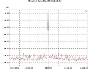
This behavior seems to be confirmed by the narrowband measurement and the corresponding very high-resolution graph. Again, the intermodulation products are visible but at very low levels.
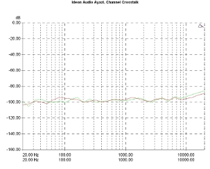
Finally, channel crosstalk was very low, with the relevant graphs in the region of -100dB, demonstrating a very slight upward trend channel leakage above 10kHz. The minimal output stage and the good design and implementation of the circuit, obviously play an important role in this performance.
Signal modulation noise (narrowband). Reference signal: 23.995,50Hz, Sample rate 96kHz.
Channel crosstalk.
Previous | Next | More Reviews

