about Audio, High Fidelity
& Home Entertainment technologies
pid: 607-2025/10/01 (v1.2)
Privacy Policy

Laboratory evaluation of the 3R USB proved a serious undertaking with some problems to solve (disclosure: some of them were never been solved…). As it is a device with only a USB input and output, the evaluation process should have been more one belonging to the telecommunications domain (needing access to some quite expensive equipment) and less to the audio domain. The solution we came up, for this review, was a mixed approach that included some basic, direct measurements at the USB stream level, to evaluate any device impact on the data stream and some indirect audio measurements to further evaluate (better: to infer) whether there is an effect on the behavior of an audio system.
The whole setup included a USB port (type A) on the computer that hosts the audio analyzer we use on a regular basis (Prism Sound dScope III), the 3R USB, a USB/SPDIF interface and, finally, a USB DAC (for the purpose of this test the Ayazi DAC from Ideon Audio was used). A special test fixture was set-up to expose the USB signal lines for probing.
The measurements performed, included eye patterns for the USB stream before and after the 3R USB (upstream and downstream respectively), eye patterns for the S/PDIF signal (at the output of the USB/SPDIF converter), and a set of standard D/A converter measurements (based on the AES-17 recommendation) with and without the use of the 3R USB. The goal was to determine whether the are measurable differences that the device under test introduces to the USB stream and to attempt to associate the quality of this stream with the quality of digital or/and analog audio signal.
The bad news is that the direct observation of a High-Speed USB signal is a demanding application: Given that an oscilloscope with a bandwidth of at least three times the bitrate is required for reliable results, at a sample rate of 480Mbps, a 1.5GHz per channel machine is needed. Texas Instruments, for example, uses a 16GHz Agilent scope for similar purposes, a piece of equipment which is quite expensive (and far from the standard in a lab mainly designed for audio equipment evaluation). Therefore, the whole evaluation procedure was performed at a Full Speed (12Mbps) bus rate, a choice that set two limitations: First, it does not reflect the behavior of the system near the limits of the data channel involved (which is obvious) and, secondly, (and most importantly) deactivates one of the 3R USB tools, the signal conditioner, because, based on what Texas Instruments says, the particular chip does not implement any loss compensation at Low Speed and Full Speed rates. However, given the common assumption that problems that occur (and potentially are corrected) at a low bitrate, become more important as the bitrate gets higher, we can reasonably assume that if the device proves to be effective at Full Speed, there is a serious chance to be even more efficient at the High-Speed rate.
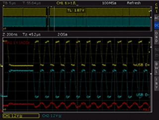
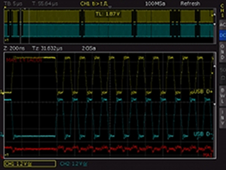
The first two graphs worth studying are the data stream itself before and after the 3R USB. These, show the signal on the two data lines (D + and D-, the USB signal is a differential one in its nature) as well as their sum (the red trace). The sum of the two signals theoretically should be zero, but in practice contains some noise. From this procedure, it is not clear where this noise comes from, but it is clear that its level is slightly lower after the 3R USB and with a different spectral content.
USB stream: Data (D + and D-) and common mode noise (MA1), 3R USB, upstream.
USB stream: Data (D + and D-) and common mode noise (MA1), 3R USB, downstream.
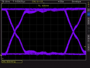
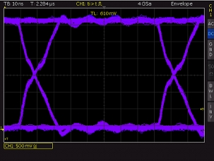
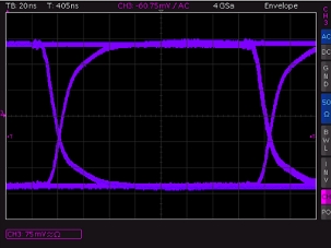
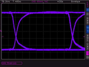
An eye pattern consists of repeated measurements (more than one signal value corresponds to the same time axis point) and shows the statistical variance of the signal both in the amplitude axis (the signal noise, distortion and transient phenomena) and in the time (horizontal) axis (the signal phase noise, or jitter). The study of the two graphs shows that 3R USB improves the USB stream. In its output, the signal has a smaller jitter (2nS versus 2.6nS), a greater slope (130mV/nS vs. 102mV/nS, therefore a lower probability for timing problems) and a slightly better eye opening (the optimum time when the system should decide on the bit value). Therefore, based on the measurements, the device works exactly as promised, improving the signal transfer conditions, even at the FS rate (which poses significantly lower requirements).
Eye pattern, USB stream, triggered on data, 3R USB, upstream.
Eye pattern, USB stream, triggered on data, 3R USB, downstream.
After that, one of the questions that can be asked is whether the improvement of the signal on the bus may affect the audio signal in the digital domain, that is, as long as it is in the S/PDIF format (a USB-to-S/PDIF signal conversion necessarily occurs within any USB DAC). The answer is "somewhat" and this is shown in the corresponding eye pattern graphs, which differ only slightly in their basic features.
Eye pattern, S/PDIF stream, triggered on data, USB/SPDIF converter.
Eye pattern, S/PDIF stream, triggered on data, USB/SPDIF converter + 3R USB.
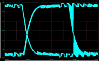
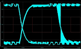
Standard measurements of the S/PDIF stream using dScope III scripts (based on the AES-17 recommendation) show a lower jitter (4.8nS vs. 5.3nS) although, given the resilience of this protocol, this is a result that is unlikely to affect the audio performance of a system. Based on the specifications, the signal is fully acceptable both with and without the 3R USB, which is shown by the corresponding eye patterns provided by the audio analyzer (using a completely different data capture and graph creation method). Here, the red squares define a template that is not allowed to overcome the opening of the eye and the relative waveform is in both cases very far away from such an event.
Eye pattern/opening, (dScope III), USB/SPDIF converter.
Eye pattern/opening, (dScope III), USB/SPDIF converter+3R USB.
Up to this point, the evaluation procedure seems to lead to the conclusion that, indeed, 3R USB has a positive effect on both the USB stream and the S/PDIF signal (albeit, at the latter, of a much less importance). The last question now is whether there is any effect on the performance of a DAC (a finding which will allow us to infer that it will also correspond to some audible changes). The answer to this question is "yes".
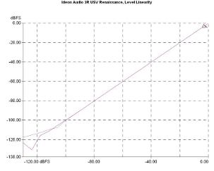
With the 3R USB at its USB port, the Ayazi DAC seemed to perform better on many critical parameters, starting from its level linearity, where the relative curve maintains a better form below -100dBFS.
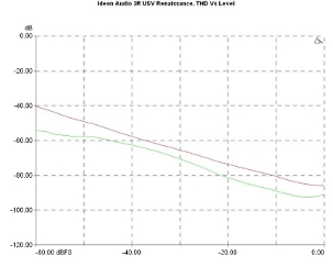
Generally, 3R USB seems to help the DAC towards its low-level signal performance. On the THD Vs Level graph, the curve corresponding to the use of the device is systematically below the curve of the standard Ayazi performance, with the differences, increasing as the level decreases.
Output level linearity. Signal frequency 1kHz, sample rate 44.1 kHz. DAC (gray curve) and DAC+3R USB (violet).
THD Vs Output level. Sample rate 44.1kHz, DAC (red curve) and DAC+3R USB (green).
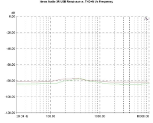
Smaller but observable differences also appear in the THD+N Vs Frequency measurements. Here the two curves differ by about 2-3dB, a phenomenon that becomes clearer in the low and high-frequency parts of the spectrum.
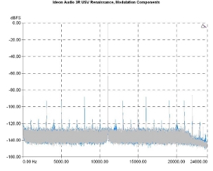
The noise-modulation spectrum shows that the presence of 3R USB results in better performance. The sum of the modulation products are at -83dBr, in the case of Ayazi and at -96dB in the case of the combination of Ayazi and 3R USB, some 13dBs lower!
THD+N Vs Frequency. Sample rate 44.1kHz, level: -1dBFS, DAC (red curve), and DAC + 3R USB (green).
Signal modulation noise (broadband). DAC (blue curve) and DAC+3R USB (gray).
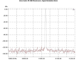
The modulation of the signal from low-frequency noise, on the other hand, seems not to be particularly affected by the presence of the 3R USB. The relevant graphs are quite similar in distribution and level, being an indirect confirmation that the system that was evaluated did not have a jitter problem either with or without the 3R USB.
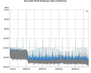
However, the most interesting result is, by far, that of the noise and interference spectrum. Here it appears that the behavior of the DAC outside the acoustic range is considerably improved by using 3R USB with the total out-of-band (>22kHz) noise measured at -87dBu and -82dBu respectively, with and without the 3R USB. This improvement also has an in-band effect (22Hz-22kHz) where the corresponding value is improved by approximately 2dBu (-85.6dBu Vs. -83.7dBu).
Signal modulation noise (narrow band), DAC (red curve) and DAC+3R USB (gray).
Noise and interference spectrum. DAC (blue curve) and DAC+3R USB (gray).
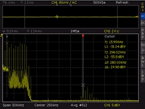
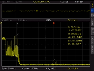
To support these findings, we finally performed a spectrum analysis focused on a frequency region somewhat outside the usual frequency limits for a digital audio product (a 500kHz bandwidth analysis centered at 250kHz). In the corresponding graphs, one can observe the similarity of the findings with those of the corresponding standard DAC measurements for noise and interference, where it is clear that the noise at the first 100 kHz of the spectrum analysis is lower when the 3R USB is in use (and an absence of noise products below the cut-off frequency, near the left edge of the graph is evident), while the system is also more clear above 250kHz.
Based on all of the above, one can infer that the way 3R USB works, at least in this particular case, is more through improving the system in terms of noise level and noise modulation and less in terms of timing issues such as jitter. Referring to the first paragraph of this page, it is legitimate to suppose that, at a higher bitrate, the results will be more significant (and probably, the jitter will become a more important factor).
Noise spectrum (500kHz, center frequency 250kHz), DAC.
Noise spectrum (500kHz, center frequency 250kHz), DAC+3R USB.
Previous | Next | More Reviews

