about Audio, High Fidelity
& Home Entertainment technologies
pid: 607-2025/10/01 (v1.2)
Privacy Policy
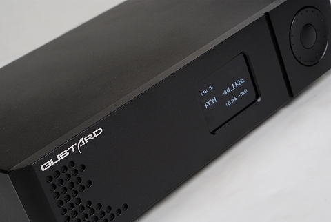
Laboratory evaluation was done through the coaxial digital input, with 24-bit/96kHz signals, unless otherwise stated. The single-ended analog output was used during the process, with the Linear Phase/Fast digital filter engaged. NOS mode was Off.
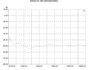
It seems that the device depends on the jitter control offered by the ESS conversion chips, as it offers significant attenuation that reaches about -50dB (a value slightly decreasing towards the very low frequencies). The digital interface itself (CS8422) does not offer such a function. The result means that the DAC-X16 is quite resilient to digital sources and/or digital signal cables of low or moderate quality.
The device itself seems to introduce only small jitter, the relevant calculations giving values between 35ps and 110ps at very low and low frequencies.
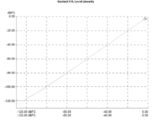
Level linearity of the device was excellent, with the graph maintaining its ideal form for signal levels under -100dBFS and displaying a good behavior down to -120dBFS, a point beyond which the noise appears to prevail.
Jitter attenuation vs jitter frequency. Signal 10kHz, injected jitter 80nS p-p.
Output level linearity. Signal frequency 1kHz, sample rate 96kHz.
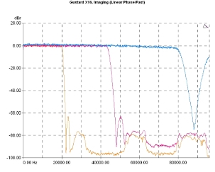
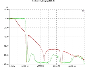
The available digital filters are quite interesting, although Gustard does not give a lot of details, here. The default Linear Phase/Fast offers the expected behavior with a gradually lower slope as the sample rate increases) and a fairly smooth stop-band.
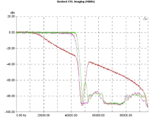
There are, also, predictable differences between the different filters in the frequency domain, with the Hybrid filter offering a better behavior in the stop-band and a slightly narrower pass-band. The Linear Phase filter combined with the internal oversampling filter in NOS Mode On (i.e. disengaged) leads to a transition band enough within the acoustic spectrum…
Low pass filter response, Linear Phase/Fast. 44.1kHz (orange curve), 96kHz (violet), 192kHz (blue).
Low pass filter response, sample rate 24-bit/96kHz. Linear Phase (green curve), Minimum Phase (orange), Hybrid (violet), Linear Phase/ NOS On (red).
…a behavior that is intensified at low sample rates (44.1kHz), where the final result is similar to that of an in-band low pass filter. Obviously, this makes the relevant option rather inadmissible, confirming Gustard's recommendations, in which the NOS Mode On should be used either at high bitrates (24/96 and above) or in combination with an upsampling algorithm preceding the device (for example, running on the media player side -for more about this refer to the Listening Sessions part of the review).
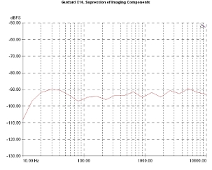
In all cases, however, the suppression of the imaging components in the audio spectrum is very good. The relevant graph (displayed here for the Linear Phase filter) is systematically below -90dBFS, for the whole measurement bandwidth (which has a range of 10kHz).
Low pass filter response, sample rate 24-bit/44.1kHz. Linear Phase (green curve), Linear Phase/NOS On (red).
Suppression of imaging components (96kHz sample rate), Linear Phase/Fast.
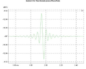
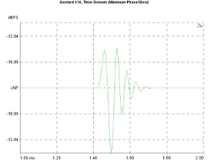
In contrast to the frequency domain, the time domain measurements offer some significant differences between the filters. The Linear Phase is the most standard, with obvious pre- and post-ringing behavior…
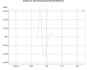
…which, practically, disappears when the NOS function is activated (with some expense in the bandwidth which is sustainable at least with a 24/96 sample rate)…
Time-domain response, 24-bit/96kHz. Linear Phase.
Time-domain response, 24-bit/96kHz, Linear Phase/NOS On.
…while the Minimum Phase filter seems to be a better approach (without pre-ringing, and with a better frequency response)…
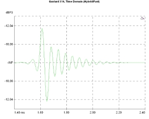
…and the hybrid filter offering the best overall behavior in the frequency domain, with minimal pre-ringing but quite a long post-ringing in the time domain. Gustard states that this behavior is more compatible with musical instruments and suggests this filter for all-around use. In any case, it is worthwhile to try all the filters and decide for yourself.
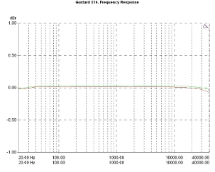
The frequency response does not offer any surprises (the device is practically flat in the entire measurement bandwidth), beyond the fact that it reveals an excellent channel balance, with the differences being well below 0.1dBr.
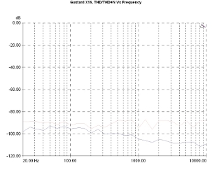
DAC-X16 distortion behavior was very good with the relevant figures being at very low levels. In relation to the signal frequency, the THD+N remains systematically around and below the -90dB level, while the THD goes down at -110dB towards the high-frequency part of the spectrum…
Frequency response, 24-bit/96kHz. 0dBr: 1kHz, -20dBFS.
Harmonic Distortion Vs Frequency, 24-bit/96kHz. Level: -1dBFS. THD+N (pink curve), THD (purple).
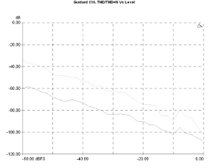
The DAC maintained very low distortion figures even at low signal levels, with the THD to be at -60dB for a -60dBFS signal and the THD+N lying just below -30dB for the same signal level. To have a percentage rate sense, in the first case we are talking about distortion values around and below 0.001%, and in the second case around and below 0.03%, a very good performance, indeed. Furthermore, distortion in high-level output conditions does not show any upward trends, an indication that the analog stage is well-designed and capable to handle signals near the 0dBFS limit of the converter.
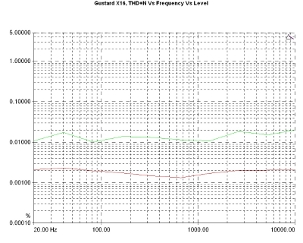
The graph of the THD+N versus signal level and frequency, visually confirms all of the above. The converter has a smooth behavior in the frequency domain, operating between 0,001-0.002% of THD+N for high-level signals and between 0.01-0.02% of THD+N for low-level signals, a performance which, in total, should be considered excellent for the price level.
Harmonic Distortion Vs Level, 24-bit/96kHz. THD+N (pink curve), THD (purple).
THD+N Vs Frequency Vs Level, 24-bit/96kHz. Level: -1dBFS, (red curve), -20dBFS (green).
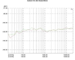
The good behavior in distortion measurements has been matched by the noise measurements. The idling channel noise remained systematically under -110dBFS even at the upper limit of measurement bandwidth (20kHz), with some hum barely visible at 50/100Hz, its level at the output measured at about 4.6 uVrms.
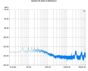
The noise and interference graph indicates a very well behaving circuit, with the relevant values in some parts of the spectrum falling under -140dBFS. There are some visible peaks that could be related to the power supply and power line noise and some limited high-frequency interference, too, but nothing to seriously complain about.
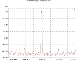
Very low-frequency signal modulation noise appears to be quite limited. In the relevant diagram, one can distinguish some components relevant to the power supply, limited to very low levels and, also, some minimal traces of possible jitter.
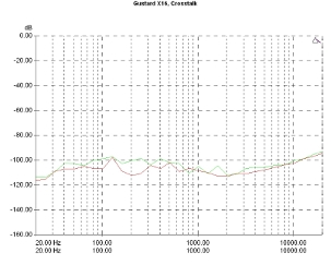
Finally, it appears that Gustard has done a very good job in the circuit and the PCB design, including the fact that cabling is practically absent, apart from the connection between the board and the transformer, which, in turn, is reflected by a very low crosstalk figure. The graph is located between -110dB and -100dB for signals up to 3kHz and remains at around -90dB towards the measurement bandwidth limit (20kHz).
Signal modulation noise (narrowband). Reference signal: 23,995.50Hz, Sample rate 96kHz.
Channel crosstalk.
Previous | Next | More Reviews

