about Audio, High Fidelity
& Home Entertainment technologies
pid: 607-2025/10/01 (v1.2)
Privacy Policy
For DO100's lab evaluation, 24/96 sample rate signals through the coaxial input were used, unless otherwise mentioned. In all cases, the DPLL sensitivity was adjusted to the "1" position (narrow band lock/low clock jitter) and the "Brickwall" digital filter was selected unless otherwise mentioned. For the analog output, the single-ended connection was used.
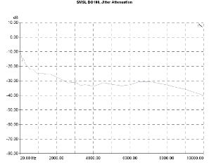
The DAC's digital interface proved to be of high quality, providing good jitter attenuation with the relevant graph lying between the -30 and -40dB points. The attenuation is lower towards the very low-frequency range. It is clear that the device can handle sources with moderate (or even bad) quality digital outputs (and cables).
Jitter introduced from the circuit itself was at typical good, low, levels, seen in designs with similar architecture and price. We calculated values around 200ps (p-p), which is far from affecting audio performance.
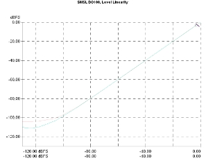
Level linearity was very good for the price range. The graph retains its ideal form down to -90dBFS and remains acceptable down to -100dBFS, a point where the noise gradually appears, to finally prevail around -110dBFS.
Jitter attenuation vs jitter frequency. Signal 10kHz, 80ns p-p injected jitter.
Output level linearity. Signal frequency 1kHz, sample rate 96kHz.
The distortion of the device proved to be very low. In relation to the signal frequency, THD+N was at -90dB, while the THD figures were at significantly lower levels, falling below -100dB in the high-frequency range.
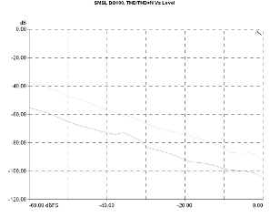
In relation to the signal level, the results were just as good. The THD+N graph just exceeds the -40dB for a -60dBFS signal level, while the THD graph was around -55dBFS for the same conditions. In addition, the analog stage shows no signs of overload when the DAC approaches its maximum output level (0dBFS). This is a really good performance for a device with such a low price.
Harmonic Distortion Vs Frequency, 24-bit/96kHz. Level: -1dBFS. THD+N (red curve), THD (green).
Harmonic Distortion Vs Level, 24-bit/96kHz. THD+N (pink curve), THD (purple).
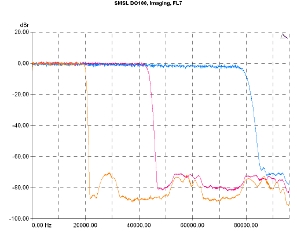
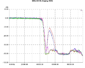
Knowing the DAC chip manufacturer we did not expect any surprises from the digital filter response. The classic brick-wall filter, shown in the relevant graph for different sample rates, has a clean rejection band, with no ripple and attenuation of -80dB.
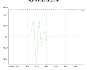
The filter options are the ones that ESS offers and add a lot of flexibility for the user to make his own choice in terms of the compromise between the filter slope/rejection behavior and its time domain response. The "slow" options (linear and minimal phase) show some significant noise content in the rejection zone…
Low pass filter response, Brickwall filter. Sample rates: 44.1kHz (orange curve), 96kHz (violet), 192kHz (blue).
Low pass filter response. Sample rates: 96kHz. Minimum Phase/Fixed-Slow (green curve), Linear Phase Slow (red), Apodizing (orange), Minimum Phase/Fast (magenta), Minimum Phase/Slow (blue), Linear Phase/Fast (purple), Brickwall (gray).
…but a noticeably better response in the time domain, without any pre-ringing effects.
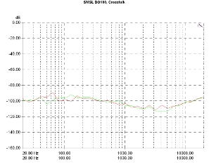
Channel crosstalk was at very low levels between -100 and -110dB, demonstrating -in practice- a very good build quality, especially in terms of signal routing and management.
For ΗΟ100 lab evaluation, the single-ended input was used, along with the single-ended TRS, 6.35mm output. The sensitivity was set to the "High" level.
The amplifier justifies the manufacturer's specs, delivering about 1.6Wrms per channel to a 32 Ohm load and 93mWrms per channel to a 600 Ohm load near its clipping point.
Static distortion measurements were at very low levels, in some cases touching fourth decimals (giving 0.0008% THD at 1kHz/32 Ohm, 0.0006% THD at 1kHz/600 Ohm, and 0.0008% IMD/SMPTE at 32 /600 Ohm, all measurements at 1/3 of the maximum power) while in the worst case the amplifier did not exceed the 0.007% (THD+N at 10KHz/600 Ohm).
The noise also remained at very low levels, as we measured -98dB(A), in reference to a level corresponding to 1/3 of the maximum power at 32 Ohm. Channel crosstalk was measured at around -55dBr, a typical value for TRS connections.
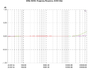
Frequency response is practically flat, with a just noticeable rise in gain above 20kHz (0.1dB) which is more prominent with 32 Ohm loads and less so with 600 Ohm loads. Towards the very low frequencies, below 20Hz, some kind of protection (possibly from DC appearing in the output) is activated which cuts out the signal. This is not a filter but some kind of switch-off behavior. Channel balance is exemplary. It is worth noting that the vertical scale on the relevant graph is 0.5dB/div!
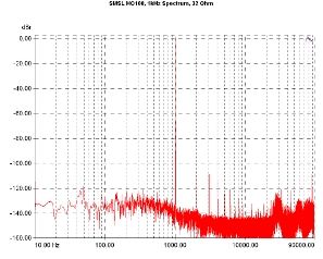
The 1kHz signal spectrum, at 1/3 of the maximum power with a 32 Ohm load, includes a distinct order of harmonics, all with levels below -100dBr and minimal noise at very high frequencies, below -120dB.
Frequency response. 0dBR: 1khz, 1/3 Pmax, 32 Ohm (green, red curve), 1/3 Pmax, 600 Ohm (orange, violet).
1kHz signal spectrum. Reference level: 1/3 Pmax, 32Ω.
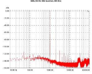
With 600 Ohm load, the amp behavior changes a little, with a slight increase in hum, at 50Hz, an indication, perhaps, that the power supply works a little harder.
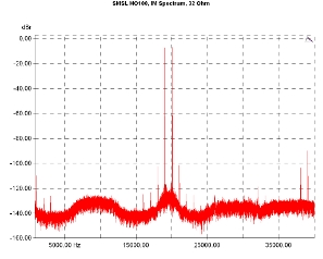
In general, the amplifier seems to be somewhat closest to its limits with 600 Ohm loads, which is reflected in intermodulation measurements. Here, using a 32 Ohm load, the third and fifth order components remain below -100dBr and the 1khz component is at -110dBr…
1kHz signal spectrum. Reference level: 1/3 Pmax, 600Ω.
Intermodulation spectrum, (19/20kHz, 1:1). Reference level: 1/3 Pmax, 32Ω.
…while with 600 Ohm load, the amplifier is characterized by higher level third and fifth order intermodulation components, near -60dBr, with the first order (1kHz) level being near the -80dBr mark. We could not think of an explanation for this behavior.
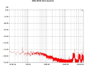
With idling inputs, the amplifier proved to be extremely quiet, proving (once again) that a switch-mode power supply, properly designed and integrated into a device, does not cause any problems. The total spectrum is below -120dB (using the 1/3 of the maximum power at 32 Ohm as a reference), with the only exception of a 50Hz peak, which, however, is below -110dBr. This is a remarkable performance, especially if one considers the price of the amplifier.
Intermodulation spectrum, (19/20kHz, 1:1). Reference level: 1/3 Pmax, 600Ω.
Noise spectrum. Reference level: 1/3 Pmax, 32Ω.
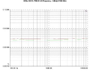
SMSL's persistence for very low distortion figures is rewarded in practice, as shown by the THD+N Vs Frequency graph, at levels near clipping (-1dBr). Here, one can see remarkably low values in the region of 0.0030% for 32 Ohm load and around 0.0025% for 600 Ohm, which are accompanied by a very smooth behavior, up to the measurement limit (10kHz).
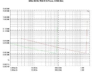
Finally, the THD+N Vs Power graph, when the amp drives 32 and 600 loads, does not hide any surprises. The relevant curves are characterized by a clear point of overload and smooth behavior around it, confirming the values of maximum power we measured statically.
THD+N Vs Frequency and output level. Reference level: Maximum power at 32/600 Ohm. -1dBr/32 Ohm (red curve), -1dB/600 Ohm (green).
THD+N Vs output power Vs Load. 1kHz signal. Load: 600Ω (green curve), 32Ω (red curve).
Previous | Next | More Reviews

