about Audio, High Fidelity
& Home Entertainment technologies
pid: 626-2026/02/21 (v1.2)
Privacy Policy
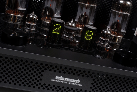
Setting a distortion limit of 1%, the I/50 delivered slightly above 50Wrms into an 8Ω load (50.5Wrms), both from the 8Ω tap and from the 4Ω tap, fully confirming the company’s claims (and its name). From the 8Ω tap, the power into a 4Ω load did not exceed 7.5Wrms, a behavior more or less expected. It is therefore evident that the amplifier is not suitable for loudspeakers whose impedance presents significant fluctuations. This is explained by the—also expected—low damping factor, which we calculated at around 9. This finding leads us to anticipate considerable variation in frequency response when driving a real-life load.
The distortion figures are reasonable for this type of circuit. The static measurements fell within the range of 0.4–0.5% for harmonic distortion and for total harmonic distortion plus noise, with a 1kHz signal, showing a clear tendency of increase relative to frequency, while intermodulation distortion was also measured at approximately 0.5%. Noteworthy is the fact that this behavior was maintained when the load was changed to 4Ω, as we measured similar values.
The amplifier proved to be exceptionally quiet, with the relevant measurement being below -99dBr(A), referenced to 1Wrms/8Ω, and with minimal contribution from the power supply (1.17mVrms).
The frequency response is “by the book” and exactly in accordance with the published specifications. The -3dB points are found just below 10Hz on the low end and just above 20kHz on the high end, but the noteworthy point is the channel matching, which is within the range of 0.1dB—an excellent performance, explained, among other factors, by the matching of the power tubes.
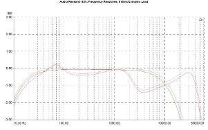
The consequences of the low damping factor are visible in the response with a complex load, with the relevant curves showing notable deviation, not so much in the low-frequency region (less than 0.5dB at 70Hz) as in the mid- and high-frequency bands, where there are differences reaching -1.5dB around 4kHz. This means that loudspeaker selection must be carried out very carefully, and loudspeakers with large impedance variations should be avoided.
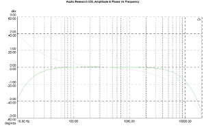
The phase diagram reveals an amplifier that ranges from +40°, in the low-frequency region to -55° near the upper limit of the response.
Frequency response for both channels. Reference level: 1/8 Pmax. 8Ω load (green/red curve), complex load (orange/purple).
Magnitude/phase response (green and pink curves, respectively).
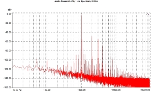
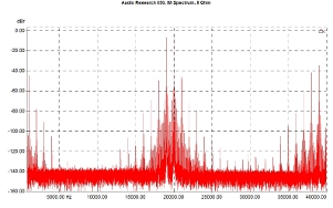
The output spectrum with a 1kHz signal, at 1/8 of maximum power into an 8Ω load, includes a rather strong second harmonic (-50dBr), followed by a familiar sequence of harmonics, which quickly drop below -100dBr (above the fourth harmonic).
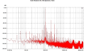
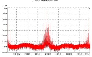
With a 4Ω load at the output, the relevant spectrum differs slightly harmonic content-wise (the second harmonic remains the strongest and at roughly the same level), which explains the similarity of the static measurements at 8 and 4Ω loads), but the stronger contribution of the power supply indicates that the latter somewhat struggles with low impedance loads at the output and -probably- constitutes a limiting factor.
Harmonic spectrum for a 1kHz signal, reference level: 1/8 Pmax/8Ω.
Harmonic spectrum for a 1kHz signal, reference level: 1/8 Pmax/4Ω.
The intermodulation spectrum with an 8Ω load includes strong third-order components (-50dBr), a first-order component (1kHz) at -45dBr, with higher-order findings rapidly decreasing in level.
With a 4Ω load, the amplifier appears to improve marginally, but once again, power-supply noise makes its appearance.
Intermodulation distortion spectrum. Signal: 19kHz/20kHz, 1:1, reference level: 1/8 Pmax/8Ω.
Intermodulation distortion spectrum. Signal: 19kHz/20kHz, 1:1, reference level: 1/8 Pmax/4Ω.
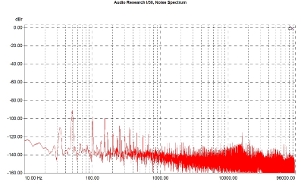
In general, however, provided that the output is not excessively loaded, the noise spectrum of the output is exemplary. The findings from hum are around and below -100dBr and fall beneath -120dBr above 1kHz, and the amplifier does not seem to pick up any high-frequency noise, at least up to the measurement limit.
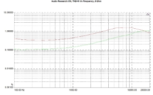
Distortion in relation to frequency shows an upward trend, with the measurement at 20kHz reaching 1% (THD+N). The values at higher power (10Wrms) are considerably higher than those measured at low power (1Wrms).
Noise spectrum. Reference level: 1Wrms in 8-Ohm load.
THD+N as a function of frequency. Output: 1Wrms/8Ω (green curve), 10Wrms/8Ω (red curve).
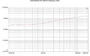
With a 4Ω load, the values do not change significantly (as we also observed in the static measurements), and the behavior as a function of frequency remains increasing.
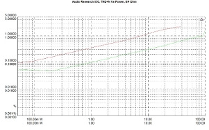
As a function of output power, the behavior of the I/50 is typical for this type of output stage. The increase in distortion is gradual, and there is no abrupt rise near overload.
THD+N as a function of frequency. Output: 1Wrms/4Ω.
THD+N as a function of output power. Load: 8Ω (green curve) and 4Ω (red curve).
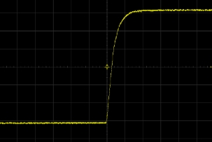
The behavior of the amplifier with a square-wave signal is as expected. The rise time is somewhat high (14.8us), but the waveform is particularly smooth without transient phenomena. The slew rate was measured at 1.86V/us.
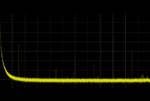
Finally, the wideband noise spectrum is quite clean, with components present at very low levels.
Response to a 1kHz square-wave signal. Output level: 25V p-p into 8Ω load. Horizontal axis: 20μs/div, vertical axis: 3V/div.
Broadband noise spectrum. Span: 100MHz, center frequency: 50MHz.
Previous | Next | More Reviews

