about Audio, High Fidelity
& Home Entertainment technologies
pid: 607-2025/10/01 (v1.2)
Privacy Policy
For the lab evaluation of the QB-9DSD, 24 bit/96kHz signals were used except where indicated otherwise. Both digital filter were used during the evaluation but the differences identified concerned - mainly- the time domain behavior while the performance of the device in noise an linearity did not appear to be affected by the type of filter selected.
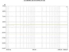
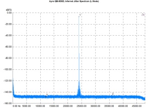
The USB interface proved good enough to handle signals with induced jitter. The relevant graph lies below -80dB for 1kHz and F S/192 signals and below -100dB for FS/4 signals proving that QB-9DSD offers a good interface capable to manage even somewhat jittery incoming streams. The device itself also seems to introduce a very low jitter. The spectrum used to calculate the inferred jitter figures includes only minimal findings that can be related to phase noise and the relevant calculation gives a value slightly below the 6pS (5.7ps). The well cared clocking circuit that is very close to the ESS dac chip is -most probably- responsible for this very good performance.
Jitter susceptibility 96kHz sample rater -3dBFS signal with 40nS sinusoidal jitter injected, FS/192 (green curve), 997Hz (red), FS/4 (Orange)
Inferred jitter spectrum. Input Signal : 24kHz/-5dBFS.
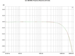
Frequency response is completely flat as expected, the high frequency roll-off being very smooth and gradual. Digital filter mode selection somewhat differentiates the behavior of the device in the pass band as shown in the graph, but the differences are rather insignificant.
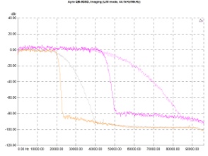
The stop-band response better displays Ayre's approach here, as one can see the nature of the apodizing filter (there are no ripples at the stop-band) and the different slopes at the transition band.
Frequency response (96kHz/24bit). Measure mode (purple, pale green curve), Listen mode (red, green curve).
Low pass filter response. 44.1kHz Measure/Listen (orange/gray curve), 96kHz Measure/Listen (violet/pink curve).
Both filters are excellent from the suppression of imaging by-products point of view. The relevant graphs (for Measure and Listen modes) are below -100dBFS. This is one of the points where the QB-9DSD offers an improvement compared to the previous version, as the later showed a clear increase in the noise at high frequencies by selecting the "Listen" mode. Probably, there are some differences in the digital filter implementation too, after all…
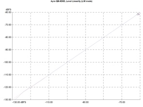
Level linearity was excellent. Using the Listen mode, the curve retained its ideal form (a straight line with a slope equal to 1) up to the limit of the measurement (-130dBFS), while in Measure mode one could observe some minimal deviation below -110dBFS. This performance ranks the QB-9DSD among the best devices we have measured lately.
Suppression of imaging components (in-band). Sample rate 96kHz, Measure/Listen (red/green curve).
Output level linearity. Signal frequency 1kHz, sample rate 96kHz, Measure/Listen (purple/pink curve).
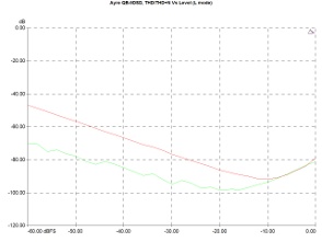
Harmonic distortion as a function of the output level was at the expected form, and remained at fairly low levels. Total distortion and noise were a little more than -50dB (for a -60dBFS signal) and harmonic distortion, without taking into account the noise was over 10dB better, as for the same signal level its value was slightly lower than -70dB. As the output level approached the 0dBFS limit, a gradual distortion increase was observed which, however, remained very low, at -80dB and shouldn't be the cause of any concern that the analog stage operates near its overload region.
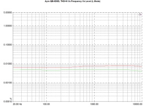
THD+N Vs Frequency graph, also, hid no surprises. Confirming the measurement above, the converter seemed to operate perfectly around -20dBFS the relative curve being near 0.005%. As the signal level approached the maximum output (-1dBFS) distortion increased noticeably, circa 0.008%, a value that remains low, whereas the behavior as the frequency increased showed no significant changes.
THD and THD+N Vs level. Sample rate 96kHz, THD+N (red curve), THD (green).
THD+N Vs Frequency. Sample rate 96kHz. Signal Level: -1dBFS (red curve), -20dBFS (green).
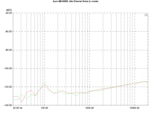
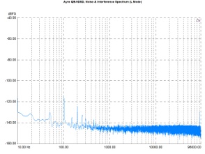
The QB-9DSD proved to be a quiet piece of equipment, as one concludes by studying the idle channel noise spectrum. For low and medium frequencies the graphs are below -120dBFS (with the exception of a peak around 100Hz -probably due to some power supply induced noise). The noise begins to rise above 1kHz its maximum value (in the limit of 20kHz) lying just below -110dBFS.
Initial impression for a good noise behavior was confirmed by the wideband noise spectrum that includes some components in the lower frequencies (50/100Hz and their harmonics and intermodulation products) but nothing beyond these. Observant readers should spot a peak just before the 96kHz limit (around -130dBFS) whose source is not known, but its level is too low.
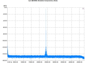
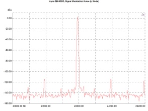
The absence of significant noise components (except those from the power supply) has its effect in shaping the signal modulation noise spectrum. There are some traces near the 24kHz fundamental which apparently are by-products of very low modulation frequencies.
This is best illustrated in the high resolution graph where one can locate components associated with the 50/100Hz and, also, some very low modulation components (but all these findings are under the -120dFS level!).
Signal modulation noise (wide band). Reference signal: 24kHz.
Signal modulation noise (narrow band). Reference signal : 23.950,20 Hz, 24bit/96kHz.
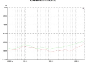
Finally, channel crosstalk was at good levels with the relevant curves lying around -90dB and without any significant change in relation to the signal frequency.

