about Audio, High Fidelity
& Home Entertainment technologies
pid: 607-2025/10/01 (v1.2)
Privacy Policy
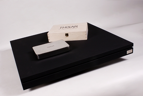
Laboratory evaluation of Silence Plus was performed with the help of a simple vibration exciter that generated and transmitted vibrations of varying frequency to a conventional rack, the upper surface of which was used as the support surface (one can assume that this is our reference surface). The process included a Linn Sondek LP12 turntable as the device on which the basic vibration measurements were made. For these measurements, a single-axis piezoelectric accelerometer (with a sensitivity 9.5mV/g) was used, placed at two different points on the LP12, the fixed metallic part of the chassis and the free to oscillate platter where the lead-in of an LP is normally located.
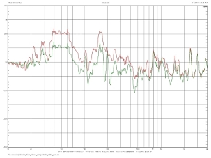
The first measurement of interest is the measurement of vibrations in the support surface. Here, it appears that there is a series of intense resonances between 100Hz and 200Hz (red curve) which are decreasing, as the frequency of the vibration increases, up to the limit of the measurement at about 4kHz. This measurement is typical of this particular rack.
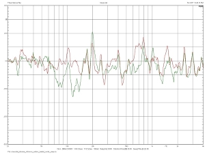
When the support surface is loaded with Silence Plus, its behavior, as expected, changes. Its character (as determined by the frequency and spacing between the resonances) remains the same in general, but their amplitude appears to be lower, with the exception of the resonance at 200Hz (green curve). This curve, i.e the behavior of the support surface when Silence Plus is already placed on it, is, in fact, the source of the vibrations with which the evaluation has been made.
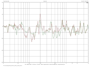
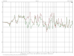
The next pair of curves explores the interfacing between the support surface and the Silence Plus. The graph includes the behavior of the former (red curve), as already measured, in relation to the vibrations measured at the center of the Silence Plus. In general, vibrations are lower, especially around the 200Hz resonance, and in the range from 500Hz upwards (green curve).
Support surface acceleration. 10Hz-4kHz sweep stimulation, with and without load (Silence Plus, green and red curves respectively).
Acceleration on the Silence Plus surface (green curve) and on the support surface (red curve). 10Hz-4kHz sweep stimulation.
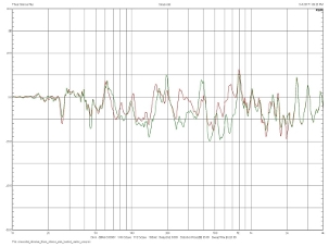
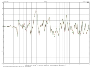
When the Silence Plus is loaded (with the Linn LP12 contacting the surface through its four small rubber support points), the vibration spectrum changes in a way that is not very predictable. The amplitude of the resonances decreases but their relative level is not consistently lower, although the peak at 200Hz is minimized (red curve). One good reason for this could be that the LP12's support points create different loading conditions which affect the movement of the Silence Plus' upper surface. If this idea is correct, a turntable with different weight or a different number (or kind) of support points could result in a different graph here.
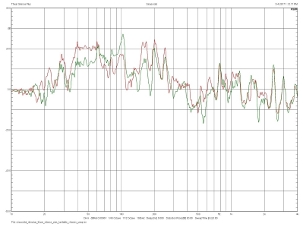
The resonance diagram of the LP12 shows the effect of Silence Plus on the fixed part of the suspended system. Here, it appears that the Silence Plus cleans the frequency range from 20Hz to 60Hz and reduces vibrations above 150Hz in a systematic way (green curve). This, in practice, means that the turntable suspension has less work to do since its fixed part is kept more stationary.
Acceleration on the Silence Plus surface with and without load (Linn LP12, red and green curves respectively). 10Hz-4kHz sweep stimulation.
Acceleration measured on the fixed (stationary) part of the Linn LP12 when placed directly on the support surface (red curve) and on the Silence Plus (green curve). 10Hz-4kHz sweep stimulation.
The last measurement is, of course, the most important, because it has been made with the accelerometer at the point where the vibrations are introduced into the electrical path of the signal, where the phono cartridge comes into contact with the record. Here, the differences are clear and it is apparent that the Silence Plus/Linn LP12 system behaves much better (green curve) than the LP12 when it is placed directly on the reference support surface (red curve). It is also quite interesting that the suppression of the vibrations is quite consistent: At least up to 2kHz, the system does not seem to present any resonance but minimizes all vibrations, verifying the Thixar's claims that an attenuation is offered at a wide range rather than at a certain frequency.
Acceleration measured on the suspended part of the Linn LP12 (platter, near the lead-in position) when placed directly on the support surface (red curve) and on the Silence Plus (green curve). 10Hz-4kHz sweep stimulation.
Acceleration on the device cover with and without the Eliminator (green and red curves respectively). 10Hz-4kHz sweep stimulation.
To evaluate the Eliminator, a preamplifier was used which was also placed in the well known by now, "reference" rack and underwent a similar excitation.
The first measurement concerns the way the device cover (which was a rather standard u-shaped surface) vibrates, with and without the Eliminator. The red curve (free vibration) defines two areas of interest between 200Hz and 300Hz, the first, and between 500Hz and 800Hz, the second, where the strongest resonances appear. The placement of the Eliminator in the center of the cover seems to improve significantly both of these areas, indicating that the method proposed by Thixar works as expected.
What is, of course, more interesting is whether the clearly documented cover vibrational behavior affects the mechanical behavior of the rest of the chassis especially near the electronics, inside the device. This preamplifier consisted of two medium-sized main PCBs and the corresponding measurements were made near the center of one of them, with and without the Eliminator in its normal place, on the cover. The diagram shows only a small positive effect on both the areas of interest (100-300Hz and 500Hz-800Hz). This finding could, of course, be device-related, probably to a significant extent: It is very likely that another chassis structure (different cover and other parts and/or different circuit fixing methods, or even different electronic components) could be more or less sensitive to external vibrations, the only way to confirm this, is through a comparative assessment of a group of devices (probably a good idea for a future article).
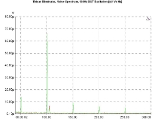
The fact that external vibrations somehow affect the device, however, albeit to a small extent, and, also, an indirect confirmation of the mechanical measurements, is shown in the last diagram presented here. It is a spectral analysis of the electrical noise measured at the output of the preamplifier (a standard measurement in all our amplifier tests) limited to the 50Hz-300Hz range, to offer a better resolution on the horizontal axis. During the measurement (with the amplifier turned on but without input signal), the chassis was submitted to mechanical excitation at a frequency of 105Hz. The choice of this frequency was based on the first diagram, where a cover resonance at this frequency is evident, and significantly suppressed by the Eliminator. In addition to the extremely disturbing fact that the 105Hz vibration appears clearly at the output as an electrical signal, it is also apparent that its level decreases by almost 50% using the Eliminator (green curve). To maintain the mental balance of all involved, the vertical axis of this graph is purposely calibrated directly in uV (microvolts), in an effort to understand the real-life scale of the phenomenon (and not the relative one through a dB scale): The 105Hz component is near a tenth of the 100Hz power supply noise component at about 65uV, and about 50% of the 50Hz power line noise (near 13uV). However, it is obvious that there is a correlation between the mechanical excitement of the chassis and the preamplifier's electrical output and Eliminator works towards its attenuation.
Acceleration measured inside the device (near the geometric center of one of the main PCBs) with and without the Eliminator (green and red curves respectively). 10Hz-4kHz sweep stimulation.
Noise spectrum at the device output with and without the Eliminator (green and red curves respectively). Reference level 1kHz/1Vrms, mechanical excitation at 105Hz.
Previous | Next | More Reviews

