about Audio, High Fidelity
& Home Entertainment technologies
pid: 607-2025/10/01 (v1.2)
Privacy Policy
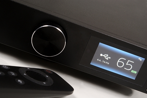
Laboratory evaluation of DO200 took place through the coaxial input, using mainly 24/96 signals (unless stated otherwise). The filter used was the Linear Fast and, for the analog signal acquisition, the single-ended output was used, set to variable mode.
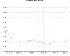
DO200's digital interface offers significant incoming jitter suppression, with the relevant graph around -65dB for a large part of the spectrum (using the default setting of the DPLL, at 5) and this behavior was retained down to very low frequencies. Using a more stringent DPLL adapting range (PLL adjusted at 1) the differences we observed were small, while in the more relaxed adapting range (PLL adjusted at 15) the device seems to have greater sensitivity in the mid, low, and very low frequencies, showing less suppression. Nevertheless, even at this mode, the graph remained below -25dB point.
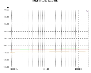
The device's excellent ability to suppress the jitter clearly reflects in the jitter susceptibility graphs, all of them being below -105dB, a performance that is among the best we've seen. This means that the DO200 is not at all sensitive to the quality of either the digital source or the digital cable used.
Jitter attenuation vs jitter frequency. Signal 10kHz, injected jitter 80nS p-p. DPLL Settings: 5 (purple curve), 1 (violet), 15 (red).
Jitter Susceptibility. Signal level -3dBFS, sample rate 96kHz, 40ns sinusoidal signal, Fs/192 (green curve), 997Hz (red), Fs/4 (orange).
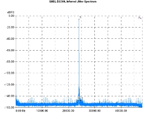
The converter itself introduces very low jitter, mainly in the region of very low frequencies where we have calculated values between 22 and 8ps.
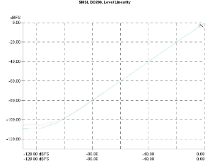
Level linearity was typically good. The graph retains its correct form down to approximately -90dBFS with only some minimal deviation observed and comfortably reaches -100dBFS. The noise seems to prevail around -110dBFS.
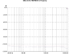
The device appears to have excellent behavior in the non-linearity domain. In relation to the signal frequency, both THD and THD+N curves are systematically lower than -100dB with the THD approaching the -110dB, a performance that should be considered as exceptional.
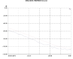
Similar behavior is shown in the level-related distortion measurements. Here, the THD is little more than -60dB for a -60dBFS signal, while the THD+N is below -50dB, also indicating very good performance. Additionally, the output stage does not seem to be approaching its clipping limits, near 0dBFS, as there is no indication of a sudden distortion increase in the upper-level region.
Harmonic Distortion Vs Frequency, 24-bit/96kHz. Level: -1dBFS. THD+N (pink curve), THD (purple).
Harmonic Distortion Vs Level, 24-bit/96kHz. THD+N (pink curve), THD (purple).
The THD+N Vs Frequency Vs Level graph summarizes all of the above: The device is characterized by a very smooth spectrum-wide behavior, with THD+N values around 0.0006% for high-level signals and around 0,002% for low-level signals.
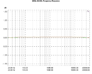
Frequency response is practically flat, without any visible cutoffs near the useful spectrum limits, which is standard behavior for a digital device. Channel balance, on the other hand, is really interesting, because it is significantly better than 0,1dB, almost zero (mind the vertical scale in the relevant graph: It is 0,5dB/Div). Probably this can be attributed to the output fine adjustment available in the PCB.
THD+N Vs Frequency Vs Level, 24-bit/96kHz. Level: -1dBFS, (red curve), -20dBFS (green).
Frequency response, 24-bit/96kHz. 0dBr: 1kHz, -20dBFS.
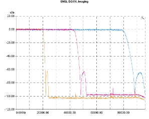
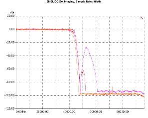
The converter's standard digital filter offers no surprises. SMSL allows the output to go up, almost to the Nyquist limit in any sample rate, with the filter slope progressively relaxing as the bitrate goes up and the cut-off zone being fairly clean.
The three different filters offer slight differences in bandwidth, with the Fast Linear offering a marginally wider range, the Minimum Phase being a moderate solution and the Slow Minimum offering the narrower bandwidth between the three, but better behavior in the time domain (the time domain response is not included here, but there is no pre-ringing).
Low pass filter response, Fast Linear. Sample rates: 44.1kHz (orange curve), 96kHz (violet), 192kHz (blue).
Low pass filter response, sample rate 24-bit/96kHz. Fast Linear (red curve), Minimum Phase (orange), Slow Minimum (magenta).
Regardless of the filter used, however, the in-band imaging components noise is particularly low. The relevant curves are close to -110dBFS and this behavior does not change even with the Slow Minimum filter. This is good news for those who choose this filter because of the better transient behavior offered.
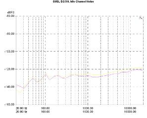
Noise performance is very good. In the idle channel measurement, the whole noise spectrum remains below -100dB up to about the 15kHz point with the graphs remaining under -110dB up to 3kHz …
Suppression of imaging components (96kHz sample rate), Fast Linear filter.
Idle channel noise spectrum.
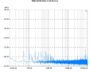
… while the noise and interference spectrum comprise of very low-level components from the power supply (50/100Hz) and some traces of interference close to 90 kHz, all of them under -120dBFS, which makes these findings of negligible importance. The total noise from the power supply does not exceed 1,6uVrms and the dynamic range of the device was estimated around 113dB.
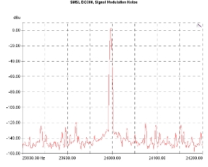
Noise modulation spectrum is quite unblemished from modulation components, the only clearly visible traces crowded around the test-tone (24kHz), pointing towards some low and very low-frequency modulation …
... which is shown by the relevant signal modulation graph. Here, one can distinguish some modulation components in the ± 200Hz range, all of them at very low levels, under -120dbu.
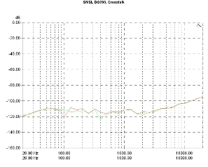
Finally, channel crosstalk reflects the quality of the circuit implementation, as both, the graphs are below -100dB for signals up to 10KHz, the worst value being just under -90dB at 20kHz, a performance that could be regarded as excellent.
Previous | Next | More Reviews

