about Audio, High Fidelity
& Home Entertainment technologies
pid: 607-2025/10/01 (v1.2)
Privacy Policy
DT-1's lab evaluation included separate measurement sessions for the Line output (to evaluate the device as a conventional DAC) and for the headphone output (to evaluate the headphone amplifier). In all cases, the coaxial input was used, along with 24-bit/96kHz sample rate signals, unless otherwise stated. The absence of an analog input has led to a problem while measuring the maximum power of the headphone amplifier, as the analyzer can output only PCM signals corresponding to a level of up to 2Vrms in the analog domain (an old, de-facto standard for the 0dBFS level in consumer digital sources). This level is much lower than required to approach the clipping limit of the device. Therefore, when needed, the maximum power considered was the figure given by the manufacturer (appropriately scaled to the corresponding load).
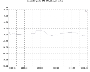
Starting from the DAC output, the digital interface offers significant suppression of the incoming jitter, with the relative curve located around -30db.
The incoming jitter susceptibility graph confirms this behavior, with all the curves being systematically under the -70dB point, a result that should be considered as good.
The jitter that the device itself introduces was detected, mainly, at very low frequencies, where the relevant calculation led to a value of around 150ps.
Jitter attenuation vs jitter frequency. Signal 10kHz, injected jitter 80nS p-p.
Jitter Susceptibility. Signal level -3dBFS, sample rate 96kHz, 40ns sinusoidal signal, Fs/192 (green curve), 997Hz (red), Fs/4 (orange).
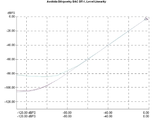
Level linearity seemed to have two sides. With the tube stage inline the measurement result was moderately good, with the curve showing visible deviations under -70dBFS and the noise to be prevalent for signal level under -90dBFS. However, using just the opamp path, the result explains the findings better: Obviously, we have to do with noise that is not related to the D/A conversion but with the tube stage. In this case, the graph retains its ideal form down to -90dBFS and the noise is prevalent for signals under -100dBFS.
In relation to the signal frequency, the THD is in the region of -70dB for most of the spectrum, while the THD+N figures are as expected, somewhat higher. It is quite interesting, in this regard, that the differences in both THD and THD+N values with and without the tube section are quite small.
Output level linearity. Signal frequency 1kHz, sample rate 96kHz.Tube Mode On (blue, pink curve), Tube Mode Off (red, purple).
Harmonic Distortion Vs Frequency, 24-bit/96kHz. Level: -1dBFS. THD+N (Tube On: blue curve, Tube Mode Off: red), THD (Tube Mode On: Pink, Tube Mode Off: Purple).
In relation to the signal level, the performance is as expected. Distortion values increase as the signal level is decreased and the most interesting part of the diagram is the one that shows the behavior of the two modes near the 0dBFS limit. Here, with the tube stage inline, there is an upward trend starting a little earlier than that with the semis-only mode. In both cases, though, the increase in distortion is small and the values remain below the -60dB level at 0dBFS.
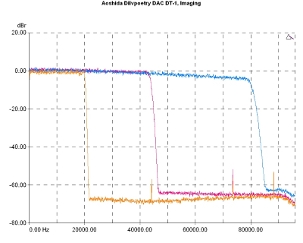
The digital filter used on the device appears to be the classic ESS' Brickwall. Dilvpoetry allows the analog stage to go up, almost to the maximum frequency at both 96kHz and 176.4kHz sample rates with a clear stopband.
Harmonic Distortion Vs Level, 24-bit/96kHz. THD+N (Tube Mode On: blue curve, Tube Mode Off: pink), THD (Tube Mode On: red, Tube Mode Off: Purple).
Low pass filter response, Fast Linear. Sample rates: 44.1kHz (orange curve), 96kHz (violet), 192kHz (blue).
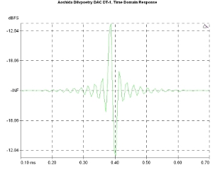
This somewhat conservative (but justified, anyway) choice of a brickwall filter leaves, of course, its footprint in the device's time-domain response, which is "by the book", with apparent pre- and post-ringing.
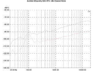
DT-1 noise behavior depends significantly on the output mode selected. With the tube stage, there is typical behavior, with a power supply-related peak at -90dBFS, while at the measurement limit, the performance reaches -75dBFS. Using the opamp path only, the results are clearly better, with the relevant curve being, systematically, in lower levels by about 15dBFS, with the exception of a hum peak at 100Hz. In voltage terms, the power supply contribution in noise is 90.4uVrms using the tube stage and 62.7uVrms without it.
Time-domain response (24-bit/96kHz)
Idle channel noise. Tube Mode On: (purple curve), Tube Mode Off: (pink).
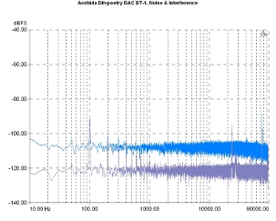
These findings are, also, confirmed by the noise and interference spectrum. The graphs show the effect of the power supply, the relationship of the noise level between the two modes, as well as the existence of some high-frequency components, although these are at low levels, under -90dBFS.
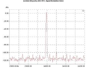
The signal modulation noise spectrum does not include any remarkable findings, confirming the fact that the power supply is quite good and that there are no jitter-related issues.
Noise and interference spectrum (broadband). Tube Mode On: (blue curve), Tube Mode Off: (purple).
Signal modulation noise. Reference signal: 23.995,50Hz, Sample rate 96kHz.
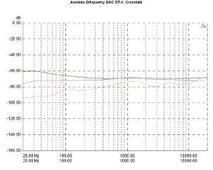
Channel crosstalk was at a typically good level in tube mode, the relevant graph being in the range of -70dB for most of the spectrum, with a slight upward trend towards the lower limit of the audio spectrum, reaching out the -60dB point. In the "Tubes Off" mode, this increase is not observed and, at the same time, the crosstalk was significantly lower, around and below -80dBs.
The headphone amplifier with 2Vrms input level yielded 512mWrms with a 32 Ohm load and 27,7mWrms when driving a 600 Ohm load.
Distortion figures were quite low, at 0.007% with a 32 Ohm load at 1kHz and 0.008% at 10 kHz, in tube mode, while, using the opamp path, they fell to 0.004%. These numbers were somewhat lower when the amplifier was connected to a 600 Ohm load, (around 0.004% for both 1kHz and 10kΗz signals).
The noise was measured at -93dBr(A), at 1/3 of power at 32 Ohm load. The good manufacturing quality was proven through the amp crosstalk measurements, at -84dB and -85dB with a 10kHz signal, using the 1/3 of max power as a level reference for the tube and the opamp path respectively.
The frequency response of the amplifier is quite interesting. It seems that there is a clear design choice here: Using the tube buffer on the signal path, a smooth attenuation, under 100Hz, is present, not exceeding 1dB at 20Hz. With the tubes out of the signal path, the response appears flat in the lower part of the spectrum. In the high-frequency part, there is also an attenuation but it is very low, since, at the limit of the measurement (60kHz), the cutoffs are -2dB and -2.8dB respectively for the opamp and the tube path.
Channel crosstalk. Tube Mode On (green, red curve), Tube Mode Off (orange, violet).
Frequency response. 0dBR: 1khz, 1/3 Pmax. 32Ω. Tube Mode On (green, red curve), Tube Mode Off (orange, violet).
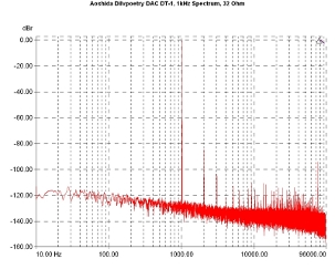
Output spectrum for a 1kHz signal input and 32 Ohm load, includes a series of harmonics, falling rapidly under the -100dB(r) level and a visible increase in noise in the low-frequency region, which -probably- is due to the tube stage (and maybe explains the choice that has been done in the low-frequency response).
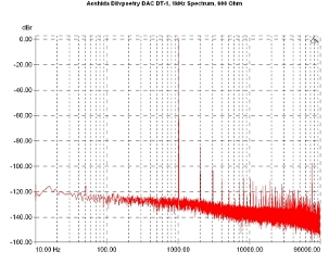
With a load of 600Ω, differences in the spectrum are really very small and one must try quite hard to identify the slightly higher-fourth harmonic and the different composition of components in the high-frequency part of the spectrum.
1kHz signal spectrum. Reference level: 1/3 Pmax. 32Ω, Tube Mode On.
1kHz signal spectrum. Reference level: 1/3 Pmax. 600Ω, Tube Mode On.
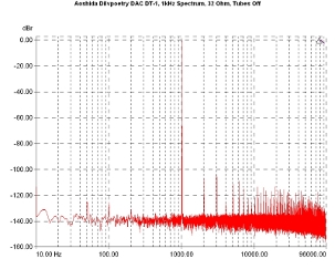
On the other hand, significant spectral differences are visible using the semi-only path mode. In this case, there is no increased noise floor at low frequencies which is around -140dB(r). This behavior better reveals the components of power supply noise and their intermodulation by-products created around the fundamental and its harmonics, which are in their entirety below the -100dB(r) level.
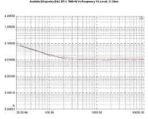
THD+N vs frequency and level graph indicates a device that has a fairly stable behavior. With 32 Ohm load, the values are between 0.01% and 0.02%, with an up-going trend below about 200Hz. At the limit of the measurement (20Hz), values are around 0.1%.
1kHz signal spectrum. Reference level: 1/3 Pmax. 32Ω, Tube Mode Off.
THD+N Vs Frequency and output level. Tube Mode On, 32Ω. Reference level: 2Vrms input. -1dBr (blue curve), -3dBr (violet), -5dBr (orange), -7dBr (red), -9dBr (green).
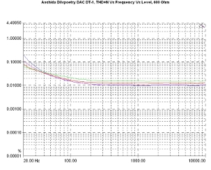
With a 600 Ohm load, this behavior does not change significantly, with distortion values ranging to the same levels and changing in a similar manner.
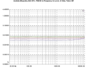
With a 32 Ohm load and bypassing the tube stage, as one would expect, the behavior changes. Here, the values ranged between 0.003% and 0.007%, depending on the level with an upward trend at high frequencies in higher levels.
THD+N Vs Frequency and output level. Tube Mode On, 600Ω. Reference level: 2Vrms input. -1dBr (blue curve), -3dBr (violet), -5dBr (orange), -7dBr (red), -9dBr (green).
THD+N Vs Frequency and output level. Tube Mode Off, 32Ω. Reference level: 2Vrms input. -1dBr (blue curve), -3dBr (violet), -5dBr (orange), -7dBr (red), -9dBr (green).
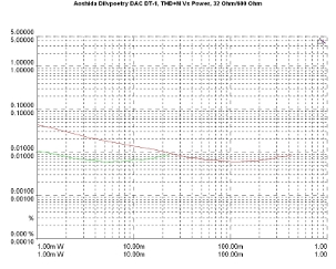
THD+N variation relative to the output power follows the conventional behavior, tending to lower values as the power rises and being significantly lower in the case of 600 Ohm loading, especially at lower power levels.
With the tube stage bypassed, the performance was even better. The 2Vrms output limit of the analyzer, unfortunately, was not allowed us to measure near the overload point.
THD+N Vs output power Vs Load. Tube Mode On. Load: 600Ω (green curve), 32Ω (red curve).
THD+N Vs output power Vs Load. Tube Mode Off. Load: 600Ω (green curve), 32Ω (red curve).
Previous | Next | More Reviews

