about Audio, High Fidelity
& Home Entertainment technologies
pid: 626-2026/02/21 (v1.2)
Privacy Policy

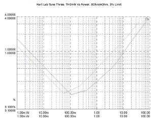
By the usual standards and with a 3% THD+N limit (a de-facto value when the circuit includes tubes), Tune Three appears rather under-powered, delivering just 37Wrms/8 Ohm and 69Wrms/4 Ohm. Of course, we are dealing with a misleading picture here, as, at this limit, the power stage is far away from actual clipping (or even the start of overloading) which is not a surprise, given the size of the power supply and the number of MOSFETs used. What happens here is a result of hARt's basic idea of a powerful amplifier with a tube sound.
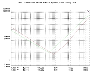
With the VAS operating without any feedback (and with the LED-based cathode biasing), all -or almost all-of the measured distortion originates from the voltage stage of the amplifier and not from the output stage, a behavior rarely observed in a conventional design in large-signal conditions. If you approach the amplifier limits the old-fashioned way, just by watching for clipping through an oscilloscope, the performance soars, with the Tune Three yielding 162Wrms, using an 8 Ohm load and 275Wrms using a 4 Ohm load. With a power increase ratio of 1.7, it is obvious that we are dealing with an amplifier that has significant power reserves and the headroom to drive difficult loudspeakers at high sound levels in moderate/large spaces as hARt promises. The damping factor was calculated near 34, leaving a margin of only minor loudspeaker-related effects on the system-wide frequency response.
Static distortion measurements confirm the view that the voltage amplifier stage imposes its performance on the output stage. THD and THD+N were in the vicinity of 1-2% with just a small variation relative to the signal frequency, as no feedback loop improves the performance, but gives higher distortion values towards the higher part of the audio spectrum, through its gain attenuation, as is usually the case. There is, also, a small distortion variation in line with the load. Thus, for an 8-Ohm load, we measured 1.7% and 1.8% THD+N respectively for 1kHz and 10KHz signals while with a 4 Ohm load the corresponding values were 1.5% and 1.7%. This unusual behavior, of slightly better performance in 4 Ohm loading conditions, compared to the 8 Ohm loading, could -also- be justified by the amplifier structure: to deliver 1/3 of the maximum power to a 4 Ohm load, the output stage (of unity gain, typically) requires a lower level output from the voltage amplifier, therefore, it introduces smaller distortion. We saw similar behavior in the IMD measurements, 1.27% and 1.18% (SMPTE) for the 8/4 Ohm loading, respectively.
The noise level was quite low, at -74dBr(A), in reference to 1Wrms/8 Ohm and the power supply-related noise was found in the 700uVrms region, justifying hARt's choices in the power supply design.
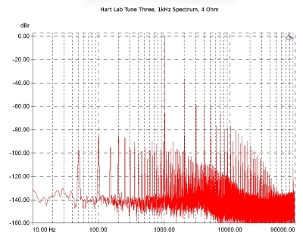
The 1kHz output spectrum, with an 8-Ohm load and a reference level corresponding to 1/3 of the maximum power, includes a strong second harmonic (near -35dBr) and a fairly smooth sequence of higher harmonics, lying below -80dBr above the fourth and below -100dBr above eighth.
With a 4 Ohm load, the behavior is slightly different, with the sequence of harmonics showing a slower attenuation rate.
Spectrum analysis with 1kHz input signal. Reference level: 1/3 of maximum power in 8-Ohm load.
Spectrum analysis with 1kHz input signal. Reference level: 1/3 of maximum power in 4-Ohm load.
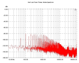
The noise spectrum (no signal at the input, referring to 1Wrms/8 Ohm) has visible traces of 50/100Hz and their byproducts, the general level falls below -80dBr and shows a quite steep attenuation for frequencies above 1kHz. The amplifier does not seem to pick up high-frequency noise from the environment (or its digital control system) as all peaks above 20kHz are below the -100dBr mark.
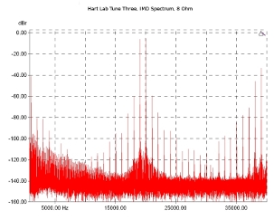
The intermodulation spectrum, using an 8-Ohm load is characterized by a strong first-order component (1kHz) at about -40dBr, with the third and fifth-order components around -60 and -75dBr respectively.
Noise spectrum. Reference level: 1Wrms in 8-Ohm load.
IM spectrum analysis with a 19/20kHz 1:1 signal. Reference level: 1/3 of maximum power in 8-Ohm load.
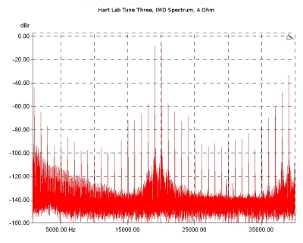
With a 4 Ohm load, the first order component decreases, reaching about -45dBr, but the levels increase in all higher-order components, with the amplifier looking much more frisky in this domain.
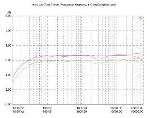
Frequency response using standard 8 Ohm dummy loads is flat, with some mild attenuation starting at about 100Hz and a total cut not exceeding 1.5dbr at 10Hz. Towards the higher frequencies, the response has good extension and at the limit of the measurement (60kHz), the attenuation is much less than 0.5dBr. Channel balance is very good, with differences in the 0.3dB region. When the load becomes complex, the response does not have significant deviations, which is reasonable given the satisfactory damping factor.
IM spectrum analysis with a 19/20kHz 1:1 signal. Reference level: 1/3 of maximum power in 4-Ohm load.
Frequency response for both channels. Reference level: 1/3 of maximum power in 8-Ohm load, (green/red curve) and in complex (simulated loudspeaker) load (orange/magenta).
THD+N relative to the frequency does not hide any surprises, given the properties of the circuit as we have understood them. With an 8 Ohm load, the amplifier performs in the region of 0.5% for very low output power (1Wrms), with the values rising in the 1.5% region for 10Wrms and at 1/3 of the maximum power. At 1/3 of the power in reference to the actual output clipping, the distortion is close to 4%.
With a 4 Ohm load, the results are better (as in static measurements, probably for the reasons already explained). For 1W/4Ω, the distortion is about 0.3%, with an upward trend above about 3kHz while at 10Wrms is in the 1% region. The distortion does not change significantly for higher power values.
THD+N as a function of frequency and output power. 1Wrms/8Ω (Green Curve), 10Wrms/8Ω (Red), 1/3 Pmax/8Ω (in reference to maximum power at 3% THD+N, orange), 1/3 Pmax/8Ω (in reference to maximum Power for visible clipping, magenta).
THD+N as a function of frequency and output power. 1Wrms/4Ω (Green Curve), 10Wrms/4Ω (Red), 1/3 Pmax/4Ω (in reference to maximum power at 3% THD+N, orange), 1/3 Pmax/4Ω (in reference to maximum Power for visible clipping, magenta).
THD+N relative to the output power and load shows -in the best way- the amplifier philosophy: here, no point marks the start of overloading but a relatively smooth (although not linear, the vertical axis is also logarithmic), continuous increasing trend as the output power rises to higher values. Typically, for 3% THD+N, the amplifier is in the 30/60W area for 8/4 Ohm loads, but we already know that the 3% limit does not depict clipping conditions in this case!
A more bold measurement shows that Tune Three can comfortably overcome the 200Wrms mark, regardless of load, as long as you are -let's say- quite flexible/tolerant with the distortion figures that can exceed 6% without any conventional traces of overloading (i.e a sharp increase in distortion values)! hARt has a clear point of view here and this is clearly visible in the diagrams…
THD+N as a function of the output power. 1kHz input signal in 8-Ohm (green curve) and 4-Ohm (red) load, input limited for 3% THD+N output distortion.
THD+N as a function of the output power. 1kHz input signal in 8-Ohm (green curve) and 4-Ohm (red) load, input limited for visible output clipping.
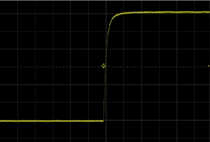
The amplifier's response to a square wave signal is very smooth, with no transient problems. The rise time was estimated at 1.7ms and the slew rate to 26V/µs, much higher than the minimum required for the specific measuring conditions (which is approximately 0.14V/µs).
1kHz square wave response. 45Vpp output voltage in 8-Ohm load. Horizontal axis: 5uS/Div, vertical axis: 7.5V/Div.
Previous | Next | More Reviews


